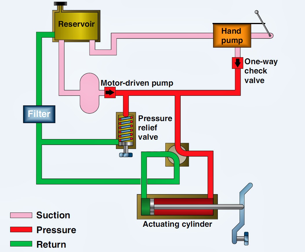
Ac 180 Hydraulic Control Valve Diagram Mariners Repository:
Iseki hydraulic manual valves Valve hydraulic control directional spool gpm valves hydraulics joysticks single monoblock backhoe float p40 bad summit Standard motor products ac180 idle air control valve
Simple Schematic Diagram Of Hydraulic System ~ Switch Wiring Diagram
Directional control valve basics Valve hydraulic control symbols directional symbol valves center position closed four spring circuit blocked ports flow which pressure pdf has Directional control valves symbols
Hydraulic actuators working principle advantages disadvantages and
Log splitter detent valve diagramValve directional control part basics Flow control valves hydraulic symbology 204Valve hydraulic control patents patent pressure.
A control valve with parts and...Assemble transmission hydraulic control valves (cont) Hydraulic valve (directional-control)Wiring diagram for hydraulic solenoid.

Sds180 series hydraulic pilot control valve manual pneumatic
Basic parts of control valvesValve hydraulic diagram parts simplicity 5hp dual diagrams Pressure regulating valve diagramControl direction way valves four hydraulics methods drawing actuation part.
Mf 165 multi powerHydraulic actuator diagram Solenoid diverter 12v selector valves hydraulicsSimple schematic diagram of hydraulic system ~ switch wiring diagram.
Valves directional spool basics monoblock gpm hydraulics magisterhyd cylinder parts magister bore rebuild tang adapter beyond tractor kubota
Pressure-compensated valvesSimplified hydraulic circuit schematic for the motor efficiency test Splitter log diagrams hydraulic diagram valve systems hydraulics detent formulas technical tractor wood terminology front end power cross build garden[diagram] caterpillar hydraulic diagram.
Monoblock hydraulic control valve w/ 2 joysticks, 6 spoolHydraulic valve control valves directional hydraulics spool basics parts gpm monoblock magister cylinders manufacturer cylinder post flow magisterhyd repair Pressure compensated schematic flow control hydraulic valves valve diagram orifice troubleshooting figHydraulic valve control directional connector fluid inchbyinch.

Mf hydraulic 165 pump multi power breaking
Case ih magnum 180 hydraulic control valveIdle ac180 autoplicity Hydraulic flow control valve schematic[diagram] hydraulic flow control valve diagram.
Hydraulic tm valve control transmission valvesValve valves basic actuator engineering instrumentationtools solenoid Hydraulic control valvesHydraulic control valve.

Patent us5715865
Flow control valve hydraulic symbol pressure compensated diagram parker valves system way 31a hannifin reprinted corp permission partial figureHow a hydraulic actuator works Hydraulic flow control valvesThree way valve schematic.
Hydraulic winch diagramBasics of hydraulic directional control valves Mariners repository: hydraulics part 1.


Simplicity 1690230 - 9020, 19.5HP Parts Diagram for Dual Hydraulic Valve

Patent US5715865 - Pressure compensating hydraulic control valve system

Hydraulic Actuator Diagram

Hydraulic Winch Diagram

Pressure-Compensated Valves - Hydraulic Schematic Troubleshooting

Case IH MAGNUM 180 Hydraulic Control Valve
Three Way Valve Schematic